Tuesday, May 21, 2013

Debugging an Xbee UART using a USB Logic Analyzer

I've been having trouble communicating with my Xbees last week and I thought the problem was bad connections.  In the end it was due to the Xbees configured as end-points and their sleep values set too aggressively.  Sleep settings are worthy of a whole blog entry by itself but this short page will focus on an easy way to debug both ASCII and binary XBee API calls.

USB Setup

The analyzer I used was a USBee-AX that plugs onto the USB port.  At first I thought the unit was defective but you only need two connections to debug the UART's TX/RX.  No need for GND or VCC connections:


Software Setup

The other missing piece was dialling in the baud rate correctly.  I run my XBees at 115200 and 2 stop bits for various reasons and the USBee-AX needed to be configured the same before data was intercepted by double clicking on the UART section for this dialog box:


The last piece was designating the TX line to be the trigger to start sampling.  You can see that in the final image as the rising edge next in the blue TX box.

Binary Output and Frame Decoding

I was very surprised to see actual binary bytes after designating line 6+7 as UART.  The section to the right shows the UART communication in-view and syncs such that it always shows the same data as the main window but in more readable form.


This data is actual serial communication at 155200 baud intercepted over a few milliseconds.  As you can
see both the 7E 08 AT commands show up along with their corresponding 7E 88 AT response.

Decoded by the Digi API frame maker we can see this is in the middle of asking for the whole Xbee state and this is the ATNT command/response.  Compare the Packet bytes below with the blue bytes above.


A great tool to debug protocol over physical wires and makes hardware tinkering more debuggable.  The setup showed me right away that there was nothing wrong with my serial transmission which led me down the road to find out the module was just sleeping.

Tuesday, May 7, 2013

Cheap Pyroelectric Infrared PIR Motion Sensor on 3.3v

My current project is focusing on a pure 3.3v setup, both MPU and sensors.  I've been experimenting with various cheap sensors from both SparkFun and eBay sellers from China to fill the various sensor "slots" my final module should have.

One of them is Motion Sensing.

The PIR Motion Sensor from SparkFun looked good at first but I was concerned with the problems it seemed to have running at 3.3v.


All the other PIR Sensors on eBay seemed to have the same setup with some onboard voltage regulator.  1.7v Voltage Dropout on these regulators prevent an already regulated 3.3v source from powering it out-of-the-box.  Or so I thought...

The even more expensive sensor from Parallax looked fine but at $11 it was going to add up with a lot of my sensors.  I felt a little more comfortable tinkering with a cheap sensor from China than the others so I ordered two sensors from two different eBay merchants at around $3.


Unreliable at 3.3v

Hooking these sensors up to my Programmable XBee with a did not go as well as I had hoped.  The sensor simply didn't work with a 3.3v VCC source just like the SparkFun sensor.  The signal was wildly erratic as if someone was moving randomly in front of the sensor:

#3064 TMP102=22.19 Door=CLOSED Motion=NO
#3068 TMP102=22.19 Door=CLOSED Motion=NO
ALARM: Motion
#3072 TMP102=22.19 Door=CLOSED Motion=NO
#3076 TMP102=22.19 Door=CLOSED Motion=YES
ALARM: Motion
#3080 TMP102=22.19 Door=CLOSED Motion=NO
ALARM: Motion
#3084 TMP102=22.25 Door=CLOSED Motion=YES
#3088 TMP102=22.25 Door=CLOSED Motion=YES
ALARM: Motion
#3092 TMP102=22.25 Door=CLOSED Motion=YES
#3096 TMP102=22.19 Door=CLOSED Motion=YES

Reliable but useless at 5v

Connecting it to a 5v source fixed the problem just like others:

#3872 TMP102=22.19 Door=CLOSED Motion=NO
#3876 TMP102=22.19 Door=CLOSED Motion=NO
#3880 TMP102=22.19 Door=CLOSED Motion=NO
ALARM: Motion
#3884 TMP102=22.19 Door=CLOSED Motion=YES
#3888 TMP102=22.19 Door=CLOSED Motion=NO
#3892 TMP102=22.19 Door=CLOSED Motion=NO
#3896 TMP102=22.19 Door=CLOSED Motion=NO
#3900 TMP102=22.19 Door=CLOSED Motion=NO
#3904 TMP102=22.25 Door=CLOSED Motion=NO

However this makes it a borderline unusable sensor since I won't have 5v on my final module.  Fortunately I stumbled on an interesting hack that most likely will work fine at 3.3v permanently.

Knowing enough to cause damage

I'm actually just getting back to hardware tinkering after a 15 year hiatus doing software.  This reminds me of learning how to code by just messing with source and seeing what happens.

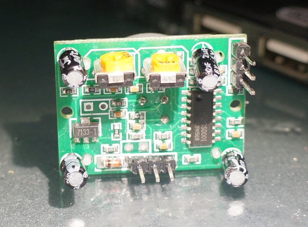
After probing the voltage regulator I confirmed that the sensor had a 7133-1 regulator which does have a 1.7v Voltage Dropout.  That's sad since I was hoping to be lucky with something closer to Parallax's design that can take input down to about 3v.


Probing around with the multimeter I confirmed the 5v in and 3.3v out on the 7133 regulator.  I also found a pure 3.3v at the lower right capacity's outer leg which rings right with what I just read about voltage regulators and noise in SparkFun's Beginning Embedded Electronics.  It looked like that capacitor would be an easier point to inject my already clean 3.3v power into the sensor than shorting out the regulator.

Easier 3.3v access?

Looking at the backside of the circuit board I could see a small trace from the newly discovered 3.3v capacitor's positive pin crossing over to... the H-pin?  After another attempt at tracking down a schematic I found something similar over at openimpulse.com.

Their schematic looked showed the sensor's 3-pin was connected directly to V-out from the regulator and the whole rest of the 3.3v trunk!  Its main purpose is to bring the BISS0001's A-line either high or low but let's use it as a 3.3v VCC instead.


Final 3.3v Hack and No Damage

Probing the three pins I found one of them being exactly 3.3v.  After moving over the gray cable over from a 5v to a 3.3v source, I plugged the other end into pin-3.  The sensor worked perfectly and reliably, just as when it was powered by 5v!

3.3v motion detecting PIR sensor done without any soldering.


Sunday, May 5, 2013

Remote Temperature Sensor using 434MHz RF Link and Arduinos

As another quick experiment to after my ElectricImp project, I decided to go the full opposite of the Imp's highlevel programming and automatic WiFi connectivity and use a low-tech 434MHz RF transmitter/receiver pair powered by Arduinos.

Hardware

The ElectricImp's WiFi connection and programming is wonderfully simple but price, power requirements, and its closed source aspect made me not invest more time here.  Instead I tried an old-school RF pair to transmit Temperature data between two Arduinos.

Transmitter

Since I'd like to keep using 3.3v sensors such as the TMP102, I got a low power 3.3v 8MHz Arduino Mini Pro to read the sensor and transmit the data to the RF Link Transmitter.  This way I don't have to translate the signals between 5v and 3.3v as i would have had to do with a regular 5v Arduino.  The soldering was a quick and dirty job where I connected the power and I2C link directly to the Arduino:


As you can see above I simply hardwired a signal line from the Arduino over to the RF transmitter using a white cable.  The connection to the TMP102 sensor is done over I2C using A4/A5 with connectors protruding from the back of the Arduino and looping back over the the sensor.

The main focus is the transmitter since the receiver will most likely be a single AC powered device.  Therefore I dug out my old Uno and a ProtoShield to hack together the receiver side.  I really just wanted to print the information on the screen but I also had to experiment with some error checking code in the end.  RF transmissions are NOT reliable as I found out.

Receiver

The final receiver unit ended up using not much more than the Uno, a ProtoShield, and an RF Link Receiver:


The code uses the VirtualWire Arduino library and was amazingly simple to use and setup.  With no antenna to speak of, I ended up with about a 100ft range which is not bad since I was feeding the transmitter a paltry 3.3v.  The RF Link specsheet says a range of 1.5 to 12v so I was planning to do some range experimentation, figuring out how supply voltage would affect range but ended up moving on to the next project that uses XBee radios instead.

Software

The code below is for both the receiver and transmitter with a simple #ifdef statements redirecting the Arduino compiler to build each sketch.  The LED usage made it easy to debug and do some manual range checking by just watching for blinks every second a GOOD reading was received.  Removing the checksum code allows you to see the corrupted messages as distance and interference increased.

Fun little project but I won't be going in this direction since I don't want to deal with cross talk interference with  10+ sensor nodes and the re-transmission protocols required.  I was also not happy with having to add an Arduino Pro Mini to each node even at $10 per node although eBay sells them for $6 now which is getting very tempting...


#include <Wire.h>
#include <VirtualWire.h>

static int tmp102Address = 0x48;
static byte kID = 0;
byte gCounter = 0;


void encode(byte ioBuffer[8], byte inTemp1, byte inTemp2)
{
  ioBuffer[0] = 't';
  ioBuffer[1] = 'e';
  ioBuffer[2] = 'm';
  ioBuffer[3] = 'p';
  ioBuffer[4] = gCounter++;
  ioBuffer[5] = kID;;
  ioBuffer[6] = inTemp1;
  ioBuffer[7] = inTemp2;
}

bool decode(byte ioBuffer[8], byte outTemp[2])
{
  Serial.print((char)ioBuffer[0]);
  Serial.print((char)ioBuffer[1]);
  Serial.print((char)ioBuffer[2]);
  Serial.print((char)ioBuffer[3]);

  Serial.print(" #");
  Serial.print((int)ioBuffer[4]);

  Serial.print(" id-");
  Serial.print((int)ioBuffer[5]);

  Serial.print(" [");
  Serial.print((int)ioBuffer[6]);
  Serial.print(',');
  Serial.print((int)ioBuffer[7]);
  Serial.print("] ");

  outTemp[0] = ioBuffer[6];
  outTemp[1] = ioBuffer[7];

  return ioBuffer[0] == 't' && ioBuffer[1] == 'e' && ioBuffer[2] == 'm' && ioBuffer[3] == 'p';
}

#define transmitter

#ifdef transmitter
void setup()
{
  Serial.begin(9600);
  Serial.println("Transmitter");
  Wire.begin();

  // Initialise the IO and ISR
  vw_set_ptt_inverted(true); // Required for DR3100
  vw_setup(2000); // Bits per sec
  vw_set_tx_pin(3);
}

void loop()
{
  byte message[8];

  Wire.requestFrom(tmp102Address, 2);  
  encode(message, Wire.read(), Wire.read());

  digitalWrite(13, true); // Flash a light to show transmitting
  vw_send(message, 8);
  vw_wait_tx(); // Wait until the whole message is gone
  digitalWrite(13, false);
  Serial.println(gCounter);

  delay(1000); // Send a temperature sample every second
}

#else // receiver
void setup()
{
  Serial.begin(9600);
  Serial.println("Receiver");

  // Initialize the IO and ISR
  vw_set_ptt_inverted(true); 
  vw_set_rx_pin(3);
  vw_setup(2000);  // Bits per sec

  vw_rx_start();       // Start the receiver PLL running
}

void loop()
{
  uint8_t buf[VW_MAX_MESSAGE_LEN];
  uint8_t buflen = VW_MAX_MESSAGE_LEN;

  if (vw_get_message(buf, &buflen)) // Non-blocking
  {
    digitalWrite(13, true); // Flash a light to show received good message

    byte id;
    byte counter;
    byte temp[2];
    decode(buf, temp);
   
    // 12bit int so using two's compliment for negative
    int TemperatureSum = ((temp[0] << 8) | temp[1]) >> 4;
    float celsius = TemperatureSum * 0.0625;
    Serial.print(celsius);
    Serial.print("C ");
    Serial.print(celsius * 9 / 5 + 32);
    Serial.println("F");
     
    delay(100);
    digitalWrite(13, false);
  }
}
#endif